

The resistance value, tolerance, and wattage rating are generally printed onto the body of the resistor as numbers or letters when the resistors body is big enough to read the print, such as large power resistors. But when the resistor is small such as a 1/4W carbon or film type, these specifications must be shown in some other manner as the print would be too small to read.
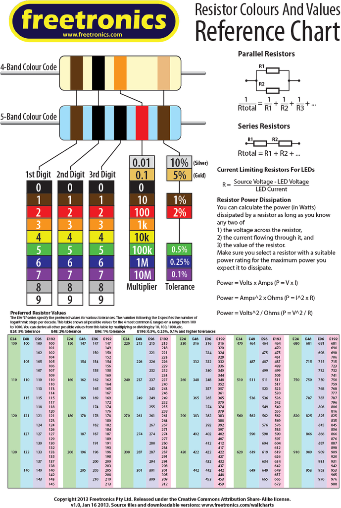
So to overcome this, small resistors use coloured painted bands to indicate both their resistive value and their tolerance with the physical size of the resistor indicating its wattage rating. These coloured painted bands produce a system of identification generally known as a Resistors Colour Code. An international and universally accepted Resistor Colour Code Scheme was developed many years ago as a simple and quick way of identifying a resistors ohmic value no matter what its size or condition. It consists of a set of individual coloured rings or bands in spectral order representing each digit of the resistors value. The resistor colour code markings are always read one band at a time starting from the left to the right, with the larger width tolerance band oriented to the right side indicating its tolerance. By matching the colour of the first band with its associated number in the digit column of the colour chart below the first digit is identified and this represents the first digit of the resistance value. Again, by matching the colour of the second band with its associated number in the digit column of the colour chart we get the second digit of the resistance value and so on. Then the resistor colour code is read from left to right as illustrated in figure.
Tips for reading resistor codes
The reading direction might not always be clear. Sometimes the increased space between band 3 and 4 give away the reading direction. Also, the first band is usually the closest to a lead. A gold or silver band (the tolerance) is always the last band.It is a good practice to check the manufacturer’s documentation to be sure about the used coding system. Even better is to measure the resistance with a multi-meter. In some cases this might even be the only way to figure out the resistance; for example when the color bands are burnt off.
Surface Mount Resistors
Surface Mount Resistors or SMD Resistors, are very small rectangular shaped metal oxide film resistors designed to be soldered directly onto the surface, hence their name, of a circuit board. Surface mount resistors generally have a ceramic substrate body onto which is deposited a thick layer of metal oxide resistance. The resistive value of the resistor is controlled by increasing the desired thickness, length or type of deposited film being used and highly accurate low tolerance resistors, down to 0.1% can be produced. They also have metal terminals or caps at either end of the body which allows them to be soldered directly onto printed circuit boards. Surface Mount Resistors are printed with either a 3 or 4-digit numerical code which is similar to that used on the more common axial type resistors to denote their resistive value. Standard SMD resistors are marked with a three-digit code, in which the first two digits represent the first two numbers of the resistance value with the third digit being the multiplier, either x1, x10, x100 etc. For example:
“103” = 10 × 1,000 ohms = 10 kiloΩ´s
“392” = 39 × 100 ohms = 3.9 kiloΩ´s
“563” = 56 × 1,000 ohms = 56 kiloΩ´s
“105” = 10 × 100,000 ohms = 1 MegaΩ
Surface mount resistors that have a value of less than 100Ω’s are usually written as: “390”,“470”, “560” with the final zero representing a 10^0 multiplier, which is equivalent to 1. For example: “390” = 39 × 1Ω = 39Ω´s or 39RΩ “470” = 47 × 1Ω = 47Ω´s or 47RΩ Resistance values below ten have a letter “R” to denote the position of the decimal point, so that 4R7 = 4.7Ω. Surface mount resistors that have a “000” or “0000” markings are zero-Ohm (0Ω) resistors or in other words shorting links, since these components have zero resistance.
If you need resistors, you can have a look at these products:
More Electronic Component,welcome to HALJIA!